NVMe Queue Depth Tuning for AI Checkpoint Workloads
GPU-to-NVMe I/O bottleneck lives in the CPU path, not the drive itself.
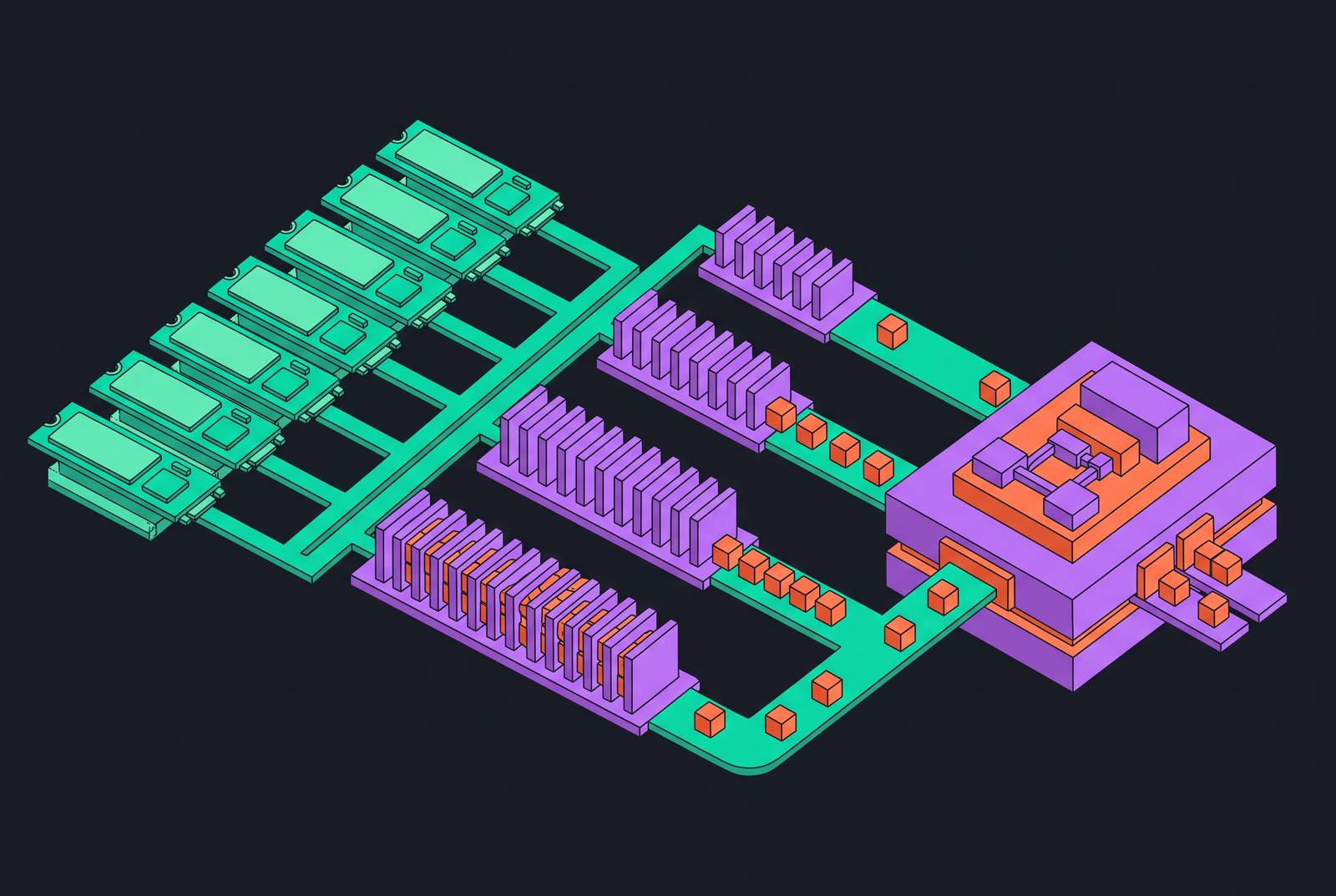
The binding constraint in AI checkpoint workloads is not NVMe media speed but the CPU-mediated software path that serializes I/O before it reaches the drive. Practitioners who frame checkpoint stalls as a storage problem misread the evidence: the drives have headroom, the accelerators do not. Checkpoint saves stall the entire training job. Every rank pauses while state drains to storage, so storage latency subtracts directly from accelerator utilization. Lablup's production study on a 63-node, 504-GPU B200 cluster found that checkpoint-save bursts reached only a fraction of available write bandwidth, and restart loading reached only a fraction of available read bandwidth, even though the storage system had headroom. NFS/RPC request queueing and transport-layer backlog rose together and were the first signals observed on the checkpoint I/O path. At 100K+ accelerator clusters, failures are routine, so checkpoint frequency is itself an optimization variable. If storage cannot sustain checkpoint bandwidth, you have to reduce frequency, and recovery spends more compute. The storage system is not the bottleneck in isolation. The I/O path from GPU HBM through to the NVMe controller is.
The five-hop I/O path and where queue depth enters the picture
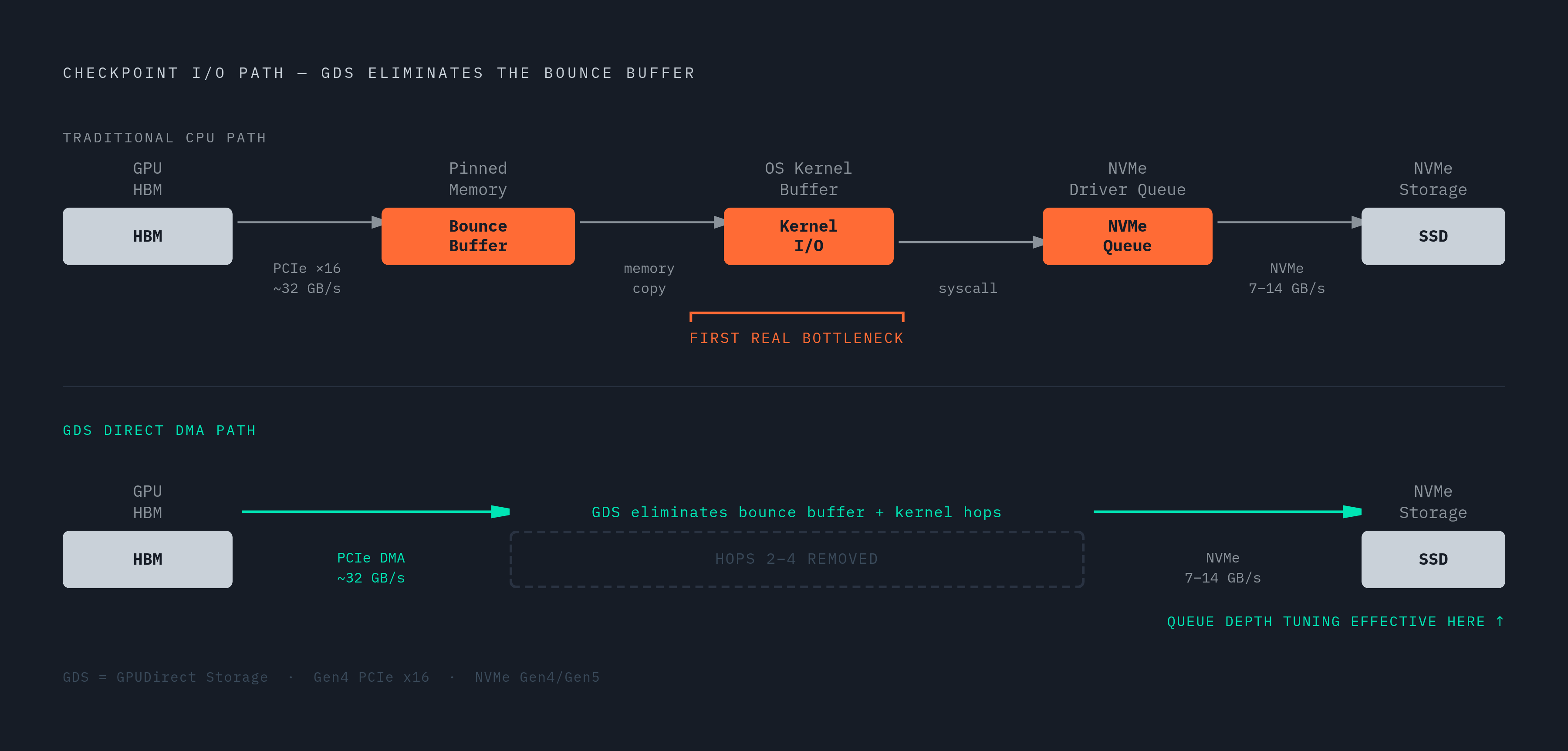
The traditional CPU-staged checkpoint path has five hops, each with its own bandwidth ceiling. Queue depth only becomes the binding constraint after the bounce-buffer hops are addressed. The five hops are GPU HBM, the PCIe bus, CPU pinned memory acting as a bounce buffer, the OS kernel buffer, and the NVMe driver queue. PCIe Gen4 x16 caps at roughly 32 GB/s, CPU DDR5 peaks around 63 GB/s, and the NVMe driver queue delivers 7 to 14 GB/s on Gen4 and Gen5 NVMe drives.
The CPU bounce buffer spans hops two through four, and it is the first real bottleneck. It forces the CPU to handle roughly double the checkpoint size in memory traffic, and it competes with DataLoader workers, NCCL communication, and the OS scheduler all at once. Only after the bounce buffer is eliminated does the NVMe driver queue become the limiting stage, and only then does queue depth tuning have leverage. Queue depth governs how many in-flight I/O requests the NVMe controller can service in parallel. Insufficient depth leaves drive parallelism idle and throttles effective bandwidth.
Eliminating the bounce buffer with GPUDirect Storage before tuning the queue
GPUDirect Storage collapses the three CPU-staged hops into zero, making the NVMe driver queue the first place queue depth tuning has full leverage. GDS uses the nvidia-fs kernel module to redirect I/O through the NVMe controller's DMA engine directly to GPU memory. No CPU cores are involved, and no DDR traffic carries checkpoint data. At the application layer, cuFile replaces pwrite. The application still uses a normal POSIX file descriptor, but cuFile routes calls through libcufile.so and nvidia-fs to the DMA engine, substituting GPU buffer addresses for CPU addresses just before DMA.
One critical side effect matters for tuning decisions: GDS bypasses the Linux page cache entirely. Data written via cuFileWrite bypasses CPU DRAM on the GDS fast path, though it can fall back to CPU-staged I/O in compatibility mode or under certain filesystem conditions. This is correct for checkpoint workloads, which are write-once and read-once on resume. It requires explicit planning for read-heavy dataset pipelines, where the page cache ordinarily does useful work. The speedup from eliminating the bounce buffer is large enough that if you skip GDS and jump directly to queue depth tuning, you are optimizing the wrong variable. With GDS in place, the effective I/O path is GPU HBM to PCIe to NVMe controller, and queue depth at the NVMe driver now directly governs how much of that path's capacity is used.
What NVMe queue depth actually controls, and what the spec limit obscures
The NVMe specification's 64K-queue ceiling is not a tuning target. The operative limit is the intersection of per-submission-queue depth, drive-side thermal behavior, and the software layer managing the queue. NVMe supports up to 64K queues with up to 64K entries each, but this spec-level ceiling is rarely the binding constraint in practice. Conflating the four distinct limits, spec, driver, application, and thermal, is the most common error practitioners make when they approach this tuning problem.
The relationship between throughput, latency, and queue depth follows Little's Law. Sustained bandwidth needs enough in-flight requests to keep the drive's internal parallelism fed, and if there are too few requests, the drive idles between completions. The NVMe driver queue depth setting, via nr_requests in the Linux block layer, is not the same as the application-level queue depth a framework like DeepSpeed exposes.
The layers of queue depth in a real training stack: driver, framework, and per-rank behavior
A production training stack has at least three independent queue depth settings that must be aligned for the NVMe controller to see the concurrency it needs. Layer one is the Linux block layer. The nr_requests per queue and the io scheduler, none or mq-deadline, control how many requests the kernel will hold in flight per NVMe namespace. Default values are tuned for general workloads, not sustained sequential writes.
Layer two is the framework. DeepSpeed's ds_config.json exposes queue_depth as a per-rank, single-stream parameter. The config-json schema default for queue_depth is 8, though DeepSpeed's own ds_nvme_tune tool typically recommends queue_depth: 32 for production NVMe and GDS workloads. In a ZeRO-3 job with many ranks writing simultaneously, the aggregate queue depth seen by the drive is the product of per-rank depth and number of ranks. DeepSpeed's block_size determines the I/O granularity that translates queue depth into actual throughput. A 1 MB block at queue depth 8 yields an 8 MB write window per rank.
Layer three is the async I/O engine. io_uring with a pinned thread per core submits I/O without blocking and allows the kernel to batch completions. The choice of async engine sets the ceiling on what the first two layers can achieve. Misalignment between layers produces exactly the failures practitioners report. Raising DeepSpeed queue_depth without raising nr_requests causes the kernel to throttle submissions before they reach the drive. Raising nr_requests without addressing the io scheduler causes reordering that converts sequential writes to random I/O. XFS filesystem tuning interacts with all three layers: stripe alignment, log configuration, and the agcount parameter affect how the filesystem serializes concurrent writes from multiple ranks.
How checkpoint workload shape determines the right queue depth target
Training checkpoint writes and inference KV cache reads have opposite queue depth optima. Conflating the two workloads produces misconfigured systems. Training checkpoints are large, sequential, burst writes at checkpoint intervals, and the goal is maximum throughput. Large I/O size, 1 MB blocks, and high queue depth per stream are correct. The drive should be fully saturated for the duration of the write burst. Low queue depth per stream with high concurrency across many streams is correct, because a deep queue from one stream increases latency for competing streams.
NVIDIA CMX, formerly ICMSP and announced at CES 2026, standardizes the offload of inference context to NVMe SSDs as an architectural pattern. The Lablup production cluster showed that restart loading, the sequential read of a checkpoint, achieved a much lower fraction of available read bandwidth than checkpoint saves. To write it in a target window, the practitioner can calculate the required number of drives and thus the aggregate queue depth the system must sustain.
What production benchmark results reveal about the queue depth and parallelism space
MLPerf Storage benchmark results show that high accelerator utilization means you must co-tune queue depth, I/O engine, filesystem, and drive count. No single variable dominates. Lablup's production study on 504 B200 GPUs with NFS storage provides the clearest real-world evidence of queue starvation. Checkpoint saves reached only a fraction of available write bandwidth not because the drives were slow but because NFS/RPC request queueing created a transport-layer backlog. The queue was not deep enough at the right layer.
StorMeshAI, in MLPerf Storage v3.0, carries file payload over two independent 400 Gb/s NDR InfiniBand and RDMA links per client and storage node, with per-chunk hash-based path selection distributing traffic across both links. A separate 50 Gb/s Ethernet bond handles management, control-plane, and filesystem metadata operations. This architectural choice keeps the queue at the storage node on balanced traffic, not hot-spot serialization. Azure Managed Lustre, also in MLPerf Storage v3.0, demonstrated checkpoint write throughput up to 642 GiB/s and recovery throughput up to 490 GiB/s. Distributed filesystem parallelism can scale throughput far beyond what any single-drive queue depth limit allows by multiplying parallelism across many drives and network paths. The common thread across high-performing submissions is explicit io_uring or RDMA-based async I/O, drive counts matched to bandwidth targets, and queue depth tuned per workload type rather than left at defaults.
A layered tuning sequence for practitioners: where to start and what to adjust in order
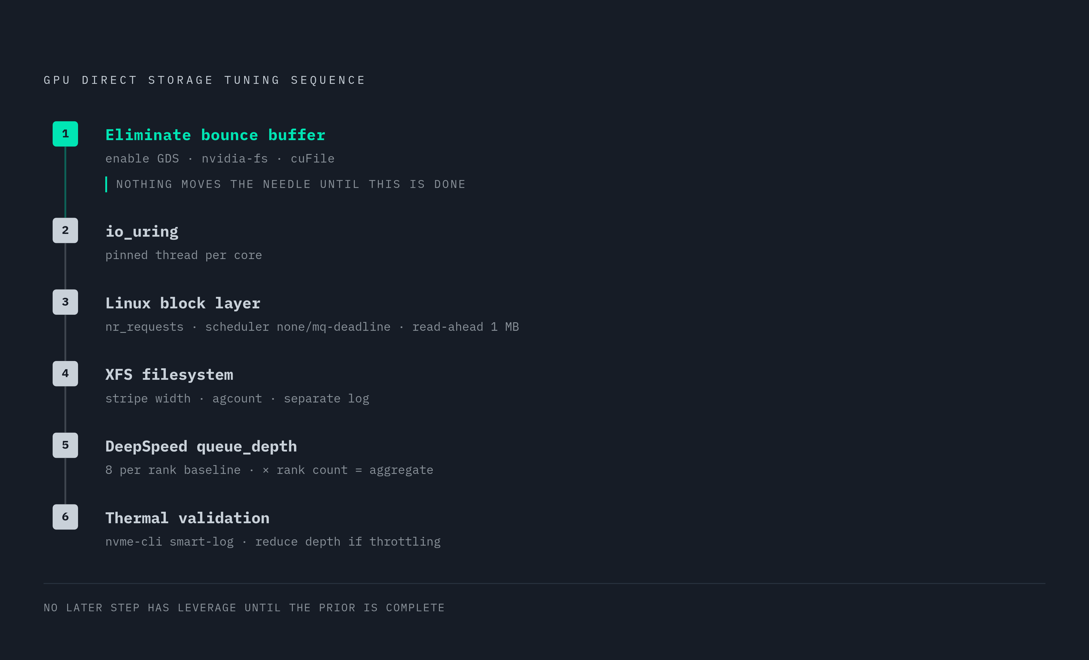
Queue depth tuning for AI checkpoint workloads is most effective when applied in a strict dependency order. Eliminate the bounce buffer first, then tune the I/O engine, then the block layer, then the framework, then validate against thermal limits. Step one is to eliminate the bounce buffer. Enable GDS with CUDA 12.3+, nvidia-fs, and cuFile, and verify with nvidia-smi or cuFile stats that writes are going through the DMA path, not the CPU path. No other tuning step has leverage until this is done. Step two is to choose the right async I/O engine. Switch from POSIX aio to io_uring with a pinned thread per core. This sets the ceiling on how many in-flight requests the kernel will sustain, and iostat should confirm that iodepth in flight matches the target. Step three is to tune the Linux block layer. Set nr_requests per NVMe queue to match the target concurrency, set the I/O scheduler to none, or mq-deadline for mixed workloads, to prevent reordering of sequential writes, and set read-ahead to a value matched to checkpoint block size of 1 MB for DeepSpeed defaults.
Step four is to tune the filesystem. For XFS, align stripe width to NVMe erase block size, tune agcount to match drive parallelism, and ensure the log is on a separate device or partition if write amplification is observed. Step five is to set framework queue depth. For DeepSpeed ZeRO-3 with GDS, start with queue_depth: 8 per rank as the stable baseline. The aggregate queue depth seen by the drive is this value multiplied by the number of ranks writing concurrently. Raise per-rank depth only after you confirm the drive is not thermal-throttling. Step six is to validate thermal behavior. Monitor drive temperature under sustained checkpoint write load using nvme-cli smart-log. If effective queue depth drops from its nominal maximum, the controller is thermal-throttling, so reduce per-rank queue_depth or add active cooling before you raise it further. For NVMe-oF configurations using RDMA or RoCE, set RDMA queue depth higher than local NVMe defaults to account for network round-trip latency adding to effective I/O depth requirements, and enable jumbo frames at MTU 9000 with Priority Flow Control to prevent packet loss from collapsing the queue.
When deeper queues stop helping: thermal limits, drive count, and the case for compression
A single correctly tuned Gen5 NVMe drive saturates at its rated sequential write speed. Beyond that point, adding queue depth adds latency without adding throughput. The queue is full but the drive cannot drain it faster. Drive-side thermal throttling reduces effective queue depth dynamically in sustained write workloads, and nvme-cli smart-log exposes the current throttle state. Operators who ignore this see checkpoint times that are reproducible in benchmarks but unpredictable in production. The Samsung PM1763 result in MLPerf Storage v3.0 illustrates what a single correctly tuned drive achieves. The Everpure FlashBlade//EXA result, 877.52 GiB/s write and 588.28 GiB/s read for a 1.25T parameter model using 30 data nodes with 1,024 simulated accelerators, illustrates what drive count and network parallelism achieve when the per-drive queue is already optimized.
Lossless compression of BF16 checkpoint tensors is the most direct way to extend the ceiling without adding hardware. BF16 exponent fields cluster over a small number of values. By splitting tensors into exponent and mantissa streams and applying entropy coding independently, compression reduces checkpoint size meaningfully without any loss of precision. Delta compression on consecutive checkpoints, XOR of consecutive states split and coded independently, achieves even higher ratios on later checkpoints. Compression reduces the data volume the tuned I/O path must carry, and it multiplies throughput without additional drives or deeper queues. It also reduces network traffic in NVMe-oF and distributed filesystem configurations. The combination Open Lake demonstrated at MLPerf Storage v3.0, io_uring parallelism, XFS tuning, and GPU-native lossless compression, is the production pattern that extracts maximum checkpoint throughput from a given drive count and queue depth budget. Practitioners who have already exhausted the queue depth tuning space should turn to compression next: it is a force multiplier on the tuned queue, not a replacement for tuning it.