GDS and NVMe-oF for Direct Storage-to-GPU Data Paths
Direct GPU storage access eliminates CPU bottlenecks that throttle LLM throughput at scale.
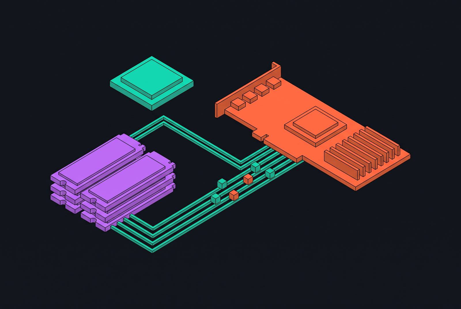
For NVMe and tiered storage for LLM inference throughput, the decisive feature is a direct path between storage and GPU memory. GDS removes CPU bounce buffers, while NVMe-oF over RDMA extends that path to shared storage. Together, they make checkpointing, weight loading, and KV cache offload less dependent on CPU memory bandwidth, making the storage path a primary infrastructure decision.
Why the CPU-staged I/O path cannot scale with LLM workloads
A conventional checkpoint write passes through five stages, namely GPU HBM read, PCIe bus from GPU to CPU, CPU pinned memory acting as a bounce buffer, OS kernel buffer, and NVMe driver queue. Each intermediate stage adds latency and competes for bandwidth. In the storage-to-GPU direction, data crosses PCIe twice, first from the drive to CPU DRAM and then from CPU DRAM to GPU memory. Those two transfers effectively halve usable bandwidth by moving the same data through an intermediate memory tier.
The CPU therefore consumes memory bandwidth on copies, leaving less for useful computation. On an eight-GPU server feeding all GPUs simultaneously, it can become the bottleneck before the drives do. A large BF16 checkpoint also makes the CPU handle roughly double the checkpoint size in memory movement, competing with DataLoader workers, NCCL communication, and the OS scheduler for DDR bandwidth. Concurrent inference requests compound the same structural cost. Open Lake's infrastructure is built with direct GPU-to-storage connectivity as its main I/O contract from the start, before a CPU-mediated path is in place.
How GDS creates a direct DMA path from storage into GPU memory
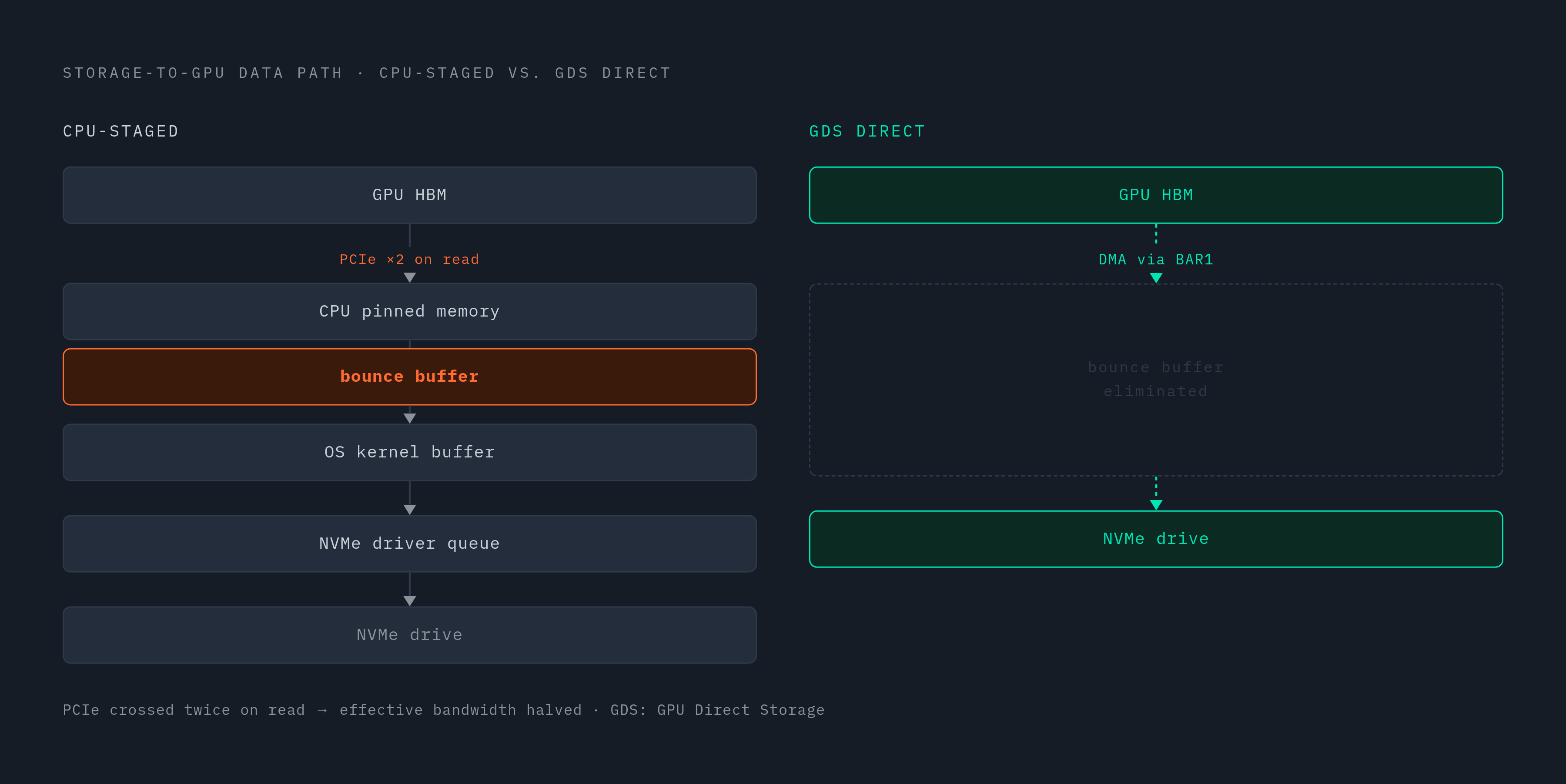
GDS removes the host bounce buffer by giving the storage layer a GPU address in place of a host address. BAR1 provides the hardware window through which GPU memory can be mapped into the PCIe address space. The nvidia-fs kernel driver uses that window to expose GPU memory to the storage layer. The file system issues I/O as usual, but the NVMe drive's DMA engine transfers data directly into GPU memory. This removes the intermediate CPU data movement without requiring the CPU to copy the payload.
Applications reach this path through cuFileRead and cuFileWrite, usually through libraries including KvikIO, DALI, cuDF, or checkpoint libraries. If the direct path is unavailable, cuFile switches to compatibility mode, so successful execution alone does not prove that CPU staging has disappeared. GDS belongs to the broader GPUDirect family and is one technology within Magnum IO. For storage systems designed around GPU-direct access, including Open Lake's, the architectural consequence extends beyond an API change. CPU mediation no longer has to be the default assumption across the storage stack.
How NVMe-oF extends the direct path to disaggregated storage over RDMA
For remote storage, the direct-write DMA engine moves from the local NVMe drive to an RDMA-capable NIC. NVMe-oF handles the transport, while the NIC writes the arriving data directly into GPU memory. The constraint is explicit, however, because GDS over the fabric requires RDMA and cannot use NVMe/TCP for the direct path. Having an Ethernet connection alone does not mean the direct path will work.
Disaggregation lets storage capacity and bandwidth scale independently of compute. That separation matters when many nodes share checkpoint pools and KV cache stores, eliminating the need for each to keep its own local copies. Western Digital's OpenFlex Data24 GDS technical brief demonstrated the architecture with RoCEv2 and RapidFlex adapters, making disaggregated NVMe-oF storage appear as local NVMe to the GPU. NVIDIA's GDS demonstration on a DGX-2 showed additive bandwidth from system memory, local NVMe, and remote storage exceeding 215 GB/s into GPU memory, compared with roughly 50 GB/s for CPU system memory paths.
Why checkpointing and weight loading expose the bounce buffer cost most visibly
A checkpoint write makes the cost of staging especially clear because a large sequential transfer has to leave GPU memory before useful work can start again. Repeating that operation throughout a week-long training job turns a transfer delay into recurring GPU idle time. Removing the bounce buffer changes the path, but total throughput still depends on the number of drives and the fabric. A single PCIe Gen5 NVMe drive peaks around 14 GB/s.
Weight loading faces the same staging delays on reads. DeepSeek-R1 in its native FP8 format is 689 GB, and a conventional loader reading from a single drive takes many minutes to populate a new replica. GDS from fast local NVMe finishes the load much faster, so the loading path matters for horizontal scale-out as well as ease of startup. Checkpoint recovery exposes the same constraint when many GPUs reload after a failure. In both cases, the operational measure is how quickly data reaches GPU memory.
Why KV cache offload turns long-context inference into a storage problem that GDS must solve
KV cache offload has a stricter latency test than bulk model loading. When a request reuses a prefix whose KV blocks have been evicted to NVMe, loading those blocks must beat recomputing the prefix. Otherwise, caching fails to improve time to first token. On an H100 serving a large model at a very long context, a single user's cache occupies a substantial fraction of HBM, and a handful of concurrent users can exhaust it. Under those conditions, NVMe offload becomes a requirement for concurrency.
The access pattern combines large sequential bursts during prefill with smaller reads during decode. It therefore requires high IOPS and sub-millisecond latency in addition to sequential bandwidth. DUAL-BLADE provides a concrete research example by assigning KV tensors dynamically to a page-cache path or an NVMe-direct path according to runtime memory availability. Its NVMe-direct path maps tensors to contiguous logical block address regions and bypasses the filesystem.
Precision also changes the pressure on that path. FP8 KV cache halves memory per token compared with BF16/FP16, while NVFP4 reduces it further. The storage design must work with the precision that the model and serving system use. MLPerf Storage v3.0, released September 1, 2026, added a KV cache workload measuring supported concurrent conversations.
What MLPerf Storage v3.0 reveals about the storage-to-GPU path as a benchmark category
Benchmarking gives operators a shared way to test whether storage paths can keep up with LLM workloads and deliver on claims of high bandwidth. MLPerf Storage v3.0 covers the named workload categories of training, checkpointing, KV cache, and vector database access. These categories expose different demands, so a result for one cannot stand in for all the others. The checkpointing workload tests at Llama 3-scale parameter counts, while the KV cache workload measures sustained concurrent conversation capacity. Both are closer to the operational questions facing LLM infrastructure teams than a generalized storage throughput figure.
The benchmark also adds an S3 data layer to the existing POSIX layer, reflecting the use of both object and file access in AI storage. MLPerf Storage v2.0, released in August 2025, showed that the systems tested could serve roughly twice as many accelerators as in v1.0. That generational improvement supplies a baseline, but it does not settle whether a system suits a particular inference workload. Standard workload definitions make such comparisons accountable. They provide a shared meaning for sufficient storage performance instead of leaving each vendor or operator to define it independently.
How lossless compression of BF16 and FP8 tensors interacts with the GDS data path
Compression can amplify GDS by reducing the number of bytes that must cross PCIe and the fabric. Lossless tensor compression, however, depends on format structure rather than treating every bit as equally compressible. BF16 contains 1 sign bit, 8 exponent bits, and 7 mantissa bits. Its exponent field has lower entropy than the sign and mantissa fields, making it the main compression target. ZipNN exploits that structure and improves on Zstd in both compression ratio and compression/decompression speed for BF16 models.
The placement of decompression matters as much as the stored size. ZipServ, published at a research conference, uses a load-compressed, compute-decompressed approach with bit-exact precision. Compressed weights load into registers, where they decode on the fly to feed Tensor Cores without passing through global memory. LCT targets a different part of the problem, namely repeated lossless BF16 encoding and decoding during training. It combines bounded Huffman coding, parallel GPU execution, fused pointwise updates, and shared GPU memory management to reduce training and fine-tuning memory use with little performance penalty.
A lossless BF16 compression experiment across all tensors of GLM-5.2 achieved strong storage reduction, but a serving comparison on 8×B300 produced slower pooled decode tokens per second despite lower steady device memory. Determining whether the saved movement outweighs decode cost on the target hardware requires profiling. BF16 results also cannot simply be transferred to FP8 because the format is part of the compression design. On-GPU decoding is architecturally consistent with GDS, whereas CPU decoding partially restores the staging bottleneck that the direct path removes.
PCIe topology alignment and transport choice as the deployment decisions that determine whether GDS delivers
The first deployment decision is physical placement. GPUs, RDMA NICs, and the relevant storage connections need aligned CPU-socket, NUMA, and PCIe-switch topology for effective peer-to-peer transfers. Most of that gain can be lost when traffic crosses a standard CPU root complex between different NUMA nodes. A PLX switch provides better peer-to-peer communication than crossing the CPU complex. Pre-deployment mapping with nvidia-smi topo -m is therefore a prerequisite to interpreting performance results.
The next decision is transport. NVMe/TCP works over commodity Ethernet and is simpler to operate, but it does not provide the GDS direct path. RDMA through InfiniBand or RoCEv2 supports that path and delivers the lowest latency. RoCEv2 needs a network built to be lossless, which includes tuning Priority Flow Control and Explicit Congestion Notification. Organizations without InfiniBand must budget for that work when they use RoCEv2 in its place.
Enabling GDS on local NVMe is a useful intermediate step before adding a parallel file system or full NVMe-oF fabric, and can be sufficient for single-node checkpoint workloads. At fleet scale, shared checkpoint pools and KV cache stores require the capacity and bandwidth pooling that local drives cannot provide. Open Lake's storage layer addresses this tier-design problem through KV cache management and RDMA-backed inference infrastructure.
Application integration must follow the hardware decisions. TensorFlow and PyTorch require explicit configuration, and ordinary file I/O does not automatically invoke GDS. Compatibility mode, unaligned writes, unsupported file systems, or poor topology can still introduce staging through system memory. The write path and any reliance on CPU page-cache access therefore require explicit planning, particularly for read-heavy dataset pipelines.
Why the storage-to-GPU path is a first-class infrastructure concern for LLM serving at scale
The common thread is that GPU utilization depends on data movement outside the GPU. Checkpointing exposes recurring idle time, weight loading constrains replica readiness, and KV cache offload places storage latency directly on the inference path. Compression can reduce that demand, but only when its decode cost does not consume the savings. Benchmarking makes these differences measurable under workload definitions that reflect the actual use of the storage tier.
Teams verify topology, enable GDS on local NVMe, profile whether the workload is I/O-bound, and evaluate NVMe-oF over RDMA when fleet-scale pooling is needed. For inference economics, the relevant question is whether the tier sustains useful GPU work and concurrent conversations without introducing avoidable transfer delays. The storage-to-GPU path is therefore a primary determinant of LLM infrastructure quality.